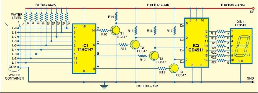
An experimenter in a facebook group that I'm a member of put up the following schematic. They asked for group members' help to give a simple explanation of the circuit. I've put the schematic here, so that I can give some feedback with a little space and some links.
The above circuit is a fluid level meter that converts the level in the container on the left into a single-digit number, from 0-9 on a seven-segment display. In this case, 0 (zero) represents the lowest level, and 9 (nine) is the highest level.
. . . . . . .
The Sensor
On the left, the level sensor is a set of ten conductors. Nine of the conductors are held high using high-resistance (560K) pull-up resistors, and one is connected directly to ground. When the water reaches a certain level it conducts between the respective conductor and ground.
Water, in its pure form, is an insulator, but most water (including drinking water) has impurities that make it slightly conductive. It is still not a good conductor, and this is why the pull-up resistors need to have relatively high resistances. In this case, when the water covers a given conductor, the conduction path to the ground pin is enough to pull the voltage down from high to low.
. . . . . . .
74147 (74HC147)
Chip name: 10-Line Decimal to 4-Line BCD (10-Line to 4-Line Priority Encoder)
This is a 74xxx (say: "Seventy-Four Hundred Series") chip that converts the "level" signal on its 10 input lines to a binary number representing the highest line active.
Important: The inputs are "active low" meaning a low value (near ground) represents an active (true) line, while a high level (near 5v) represents false.
As the water rises, it covers higher and higher pins, grounding each one it covers. Remember that, normally, these were held high by very high-value resistors. When the water provides a conductor to ground, it pulls the line down close to zero.
Again. the 74147 places a binary number on its output, which represents the number of the highest of its input pins that are at ground. You can see this in the truth tables, here:
[pdf] 74147 (74HC147) datasheet
. . . . . . .
What is 'HC'?
The 74xxx series of chips were originally a very popular series of
TTL (Transistor-Transistor-Logic) chips. These chips, their pin-outs, and their functions have since been remade using High-speed CMOS. This is what the HC in the number signifies. It is the old TTL chip's function and pin-out, just implemented with CMOS technology.
Though the logic functionality and pin-outs are exactly the same as the old
TTL logic chip, the HC may be important in this circuit. This is because one advantage of
CMOS is that it has very high input impedance, and that may be needed to make this particular circuit work with the high resistances provided by water-conduction.
. . . . . . .
The Transistors and Pull-Up Resistors
As far as I can tell these four transistors (T1-T4) are merely used as inverters, and in this circuit, they can probably be replaced with inverters. Essentially, the 74147 chip has an active low output (see datasheet linked above), meaning that 0 represents true.
For example: in active-high (what most would consider 'normal') representations, the binary output '1100' is a binary representation of the decimal number '12' (8+4). In active-low logic, the low signal (0) is the number, so '1100' represents 3 (2+1).
The input to the next chip is active-high (i.e., 'normal'), so the output lines have to be inverted. This is the purpose served by the transistors and 33K pull-up resistors.
. . . . . . .
CD4511
This chip converts the BCD encoded number on its input to proper patterns needed to drive each segment LED in a 7-segment, common cathode (common ground) display.
Not only does this chip convert the BCD input to the correct set of segments for each digit, it also provides high current on its outputs, in order to drive the LEDs. The resistors are current limiters and serve to protect the chip from short-circuit conditions.
This chip is also implemented in CMOS (Complimentary Metal Oxide Silicon). Here is the data-sheet:
[pdf] CD4511B datasheet
. . . . . . .
Caveats
I've not built this circuit. I've just produced this quick analysis, by eye-balling the diagram, so that I could answer my fellow experimenter's call for feedback about it. Again: This is quick and dirty. I have not tested the circuit or my advice about it.
-djr
2012-11-01 11:09


